
Introduction
I am going to share a small project I did a few days ago. I wanted to use the Raspberry Pi to monitor the temperature in my house and ideally to do it over the internet, so I started looking for a temperature sensor. The first problem is that the Raspberry Pi doesn´t have an Analog to Digital converter, so its GPIO are strictly digital, meaning that simple temperature sensors that output the temperature as a voltage in a range cannot be used directly.
So looking around my house I discovered I had a LaunchPad MSP430 (version G2231) from Texas Instrument, which comes luckily equipped with an internal temperature sensor. I thought I could connect the MSP 430 to the Raspberry Pi so that the latter could read the temperature values from the former. Then I could put the data in a MySQL database on the Rpi side and build a web server to plot that data.
MSP 430
First, we need to set up the MSP 430 to read the temperature values from its internal sensor using an ADC. Then we can set up the i2C in slave transmitter mode (the RPi can only work as a master). If you are starting with the MSP 430, I would recommend taking a look at its user guide and then to analyze some of the examples that come with Code Composer. It has a great debugger that allows you to stop the execution at any moment, look and modify the registers, step by step execution, etc.
Temperature Sensor + ADC
The temperature sensor is described briefly on page 550 of the user guide. It can be sampled by the ADC if we select the register INCx1010 INCHx=1010. Let’s take a look at the code. I used a lot of it from the examples, is not bad if you know what you are doing, but you need to be careful and can´t simply copy and paste different examples.
#include <msp430g2231.h>         // It has the definitions for all the registers, modes, etc.

unsigned int temp;               // holds ADC result
char SLV_Data = 0;                     // Variable for transmitted data

int main(void)
{
      WDTCTL = WDTPW + WDTHOLD;            // Stop watchdog

      ADC10CTL1 = INCH_10 + ADC10DIV_3;         // Select Channel 10 and clk divided by 4
      ADC10CTL0 = SREF_1 + ADC10SHT_3 + REFON + ADC10ON + ADC10IE;      // Set Reference value Enable interrupts and turns on the ADC10
      TACCR0 = 30;                              // Delay to allow Ref to settle. Definition in the user guide
      TACCTL0 |= CCIE;                          // Interrupt enable for the Capture Compare
      TACTL = TASSEL_2 | MC_1;                  // Source clock TACLK = SMCLK, Count mode :Up

      _EINT();                                  // General Interrupt Enable

while(1)
  {
     ADC10CTL0 |= ENC + ADC10SC;             // Sampling and conversion start
     temp = ADC10MEM - 50;
  }
}

#pragma vector=ADC10_VECTOR
__interrupt void ADC10_ISR (void)
{
        SLV_Data = temp-50;             // To the data readed from the ADC (range 0-1023) substract 50.
}

#pragma vector=TIMERA0_VECTOR
__interrupt void ta0_isr(void)
{
    ADC10CTL0 |= ENC;                     // Enable conversion
    TACTL = 0;                            // Clear the Timer A control register
}
This is the code for the ADC conversion. If you have any doubt about what I did you can ask in the comments, and look at the User Guide from Texas Instrument. Also, I found really useful to look at the msp430g2231.h To access that file you can hold the ctrl button while you click on it, and it will open in a new tab. There you can see what all those TACTL, ADC10CTL0, etc. are
There is one thing to be noted and is that the value read by the ADC is 10 bits long, however for 2i2 we need packages of 8 bits of data, of course we could split the package of 10 into two packages of 8 bits, one of them containing 6 dummy zeroes, but here comes the trick: the whole range of the thermometer is not needed. A normal house temperature doesn´t range from -50 C to +80 C, so we can omit the two most significant bits (MSB), and make substract or add a value to the variable so a normal temperature stays approx. in the middle range (around 128). That’s why I subtracted 50, so now cold temperatures in the house correspond to 90 while warm ones stay around the 140.
i2C Communication Implementation
Now that we have the value of the temperature in the variable LDta SLVData we need to send it to the Raspberry Pi. We are going to use i2Ci2C for its simplicity. Other protocols such as UART or SPI are somewhat more complicated to implement.
First let’s take a look at the code, here I combined the previous part with this new one so this is the final code:
#include <msp430g2231.h>

char SLV_Data = 0;                     // Variable for transmitted data
char SLV_Addr = 0x90;                  // Address is 0x48
int I2C_State = 0;                     // State variable

unsigned int temp;            // holds  ADC result
unsigned int IntDegC;

int main(void)
{
  WDTCTL = WDTPW + WDTHOLD;            // Stop watchdog
  if (CALBC1_1MHZ==0xFF)               // If calibration constants erased
  {
    while(1);                          // do not load, trap CPU!!
  }
  DCOCTL = 0;                          // Select lowest DCOx and MODx settings
  BCSCTL1 = CALBC1_1MHZ;               // Set DCO
  DCOCTL = CALDCO_1MHZ;

  ADC10CTL1 = INCH_10 + ADC10DIV_3;         // Temp Sensor ADC10CLK/4
  ADC10CTL0 = SREF_1 + ADC10SHT_3 + REFON + ADC10ON + ADC10IE;      // Enable interrupts.
  TACCR0 = 30;                              // Delay to allow Ref to settle
  TACCTL0 |= CCIE;                          // Compare-mode interrupt.
  TACTL = TASSEL_2 | MC_1;                  // TACLK = SMCLK, Up mode.

  P1OUT = 0xC0;                        // P1.6 & P1.7 Pullups
  P1REN |= 0xC0;                       // P1.6 & P1.7 Pullups
  P1DIR = 0xFF;                        // Unused pins as outputs
  P2OUT = 0;
  P2DIR = 0xFF;

  USICTL0 = USIPE6+USIPE7+USISWRST;    // Port & USI mode setup
  USICTL1 = USII2C+USIIE+USISTTIE;     // Enable I2C mode & USI interrupts
  USICKCTL = USICKPL;                  // Setup clock polarity
  USICNT |= USIIFGCC;                  // Disable automatic clear control
  USICTL0 &= ~USISWRST;                // Enable USI
  USICTL1 &= ~USIIFG;                  // Clear pending flag
  _EINT();

  while(1)
  {
     ADC10CTL0 |= ENC + ADC10SC;             // Sampling and conversion start
     temp = ADC10MEM - 50;

  }
}

//******************************************************
// USI interrupt service routine
//******************************************************
#pragma vector = USI_VECTOR
__interrupt void USI_TXRX (void)
{
  if (USICTL1 & USISTTIFG)             // Start entry?
  {
    P1OUT |= 0x01;                     // LED on: Sequence start
    I2C_State = 2;                     // Enter 1st state on start
  }

  switch(I2C_State)
    {
      case 0: //Idle, should not get here
              break;

      case 2: //RX Address
              USICNT = (USICNT & 0xE0) + 0x08; // Bit counter = 8, RX Address
              USICTL1 &= ~USISTTIFG;   // Clear start flag
              I2C_State = 4;           // Go to next state: check address
              break;

      case 4: // Process Address and send (N)Ack
              if (USISRL & 0x01)       // If read...
                SLV_Addr++;            // Save R/W bit
              USICTL0 |= USIOE;        // SDA = output
              if (USISRL == SLV_Addr)  // Address match?
              {
                USISRL = 0x00;         // Send Ack
                P1OUT &= ~0x01;        // LED off
                I2C_State = 8;         // Go to next state: TX data
              }
              else
              {
                USISRL = 0xFF;         // Send NAck
                P1OUT |= 0x01;         // LED on: error
                I2C_State = 6;         // Go to next state: prep for next Start
              }
              USICNT |= 0x01;          // Bit counter = 1, send (N)Ack bit
              break;

      case 6: // Prep for Start condition
              USICTL0 &= ~USIOE;       // SDA = input
              SLV_Addr = 0x90;         // Reset slave address
              I2C_State = 0;           // Reset state machine
              break;

      case 8: // Send Data byte
              USICTL0 |= USIOE;        // SDA = output
              USISRL = SLV_Data;       // Send data byte
              USICNT |=  0x08;         // Bit counter = 8, TX data
              I2C_State = 10;          // Go to next state: receive (N)Ack
              break;

      case 10:// Receive Data (N)Ack
              USICTL0 &= ~USIOE;       // SDA = input
              USICNT |= 0x01;          // Bit counter = 1, receive (N)Ack
              I2C_State = 12;          // Go to next state: check (N)Ack
              break;

      case 12:// Process Data Ack/NAck
              if (USISRL & 0x01)       // If Nack received...
              {
                P1OUT |= 0x01;         // LED on: error
              }
              else                     // Ack received
              {
                P1OUT &= ~0x01;        // LED off
                SLV_Data++;            // Increment Slave data
              }
              // Prep for Start condition
              USICTL0 &= ~USIOE;       // SDA = input
              SLV_Addr = 0x90;         // Reset slave address
              I2C_State = 0;           // Reset state machine
              break;
    }

  USICTL1 &= ~USIIFG;                  // Clear pending flags
}

#pragma vector=ADC10_VECTOR
__interrupt void ADC10_ISR (void)
{
        SLV_Data = temp-50;
}

#pragma vector=TIMERA0_VECTOR
__interrupt void ta0_isr(void)
{
    ADC10CTL0 |= ENC;
    TACTL = 0;
}
Now, this part is slightly more complicated. Usually, people rely on a library to ease i2C operations, here the whole implementation of the i2C state machine is displayed. You don’t really need to go through all the operations, but if you are curious, with the user guide you should be able to decode what the code is doing. Is also complicated to debug an i2C slave transmitter code since you need a master to generate the clock signal and to send the address, etc.
Once this code is compiled and pushed into the MSP 430, we are ready to jump to the RPi side.
Raspberry Pi
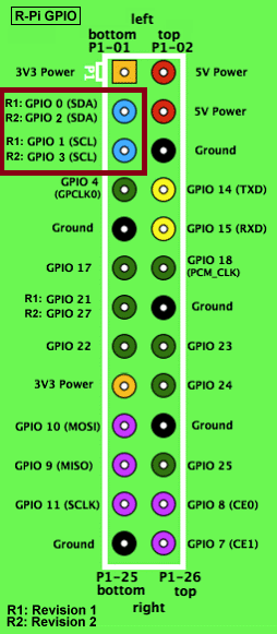
The first thing to do in the RPi is the interconnection for the i2Ci2C protocol. The pin 1.6 is SCL and the pin 1.7 is SDA so the should be connected respectively to Pin 5 and Pin 3 of the RPi (Model B 512 Mbytes RAM).
We should also add a pull-up resistor on those lines to ensure the pins are never floating. I choose values of 2KΩ2KΩ and they are working just fine.
Turn for the software side on the raspberry pi. First is to add the i2Ci2C modules to the kernel. I will not enter on much more detail here. There is an excellent guide that will take you through the process here.
After that, if you run $ i2cdetect -y 1 you should see your MSP430 listening for your orders.
pi@raspberrypi ~ $ sudo i2cdetect -y 1
     0  1  2  3  4  5  6  7  8  9  a  b  c  d  e  f
00:          -- -- -- -- -- -- -- -- -- -- -- -- --
10: -- -- -- -- -- -- -- -- -- -- -- -- -- -- -- --
20: -- -- -- -- -- -- -- -- -- -- -- -- -- -- -- --
30: -- -- -- -- -- -- -- -- -- -- -- -- -- -- -- --
40: -- -- -- -- -- -- -- -- 48 -- -- -- -- -- -- --
50: -- -- -- -- -- -- -- -- -- -- -- -- -- -- -- --
60: -- -- -- -- -- -- -- -- -- -- -- -- -- -- -- --
70: -- -- -- -- -- -- -- --
Now is the turn for the python code to obtain the values every minute (you can choose whatever you want). I decided to store the value in a MySQL database. I found this guide, that was perfect! I did mostly the same except for adding the field Zone, as I only had one thermometer, it is not needed.
sudo apt-get install mysql-server python-mysqldb
Once completed we can go ahead:
$ mysql -u root -p
Enter password:
mysql> CREATE DB temps;
mysql> USE temps;
mysql> CREATE USER 'monitor'@'localhost' IDENTIFIED BY 'password';
mysql> GRANT ALL PRIVILEGES ON temps.* TO 'monitor'@'localhost'
mysql> FLUSH PRIVILEGES;
mysql> CREATE TABLE tempdat (tdate DATE, ttime TIME, temperature NUMERIC);
#!/usr/bin/env python
import time
import os
import sys
import MySQLdb
import smbus

bus = smbus.SMBus(1)
address = 0x48;

db = MySQLdb.connect("localhost", "monitor", "password", "temps")
curs=db.cursor()

def readTemp():
        temp = bus.read_byte(address)
        return temp

while True:
    time.sleep(60)    # wait for 60 seconds to record next temperature
    temp = readTemp();

    print (temp)  # Used for debugging
    time.sleep(1)
    curs.execute ("""INSERT INTO tempdat values(CURRENT_DATE(), NOW(), %s)""",temp)

    db.commit()
All pretty simple stuff. Now are system is mainly completed but data is useless unless we can access it! So I created a web server that will serve a website plotting the data. Now we have our database ready to be populated. Lets then get to our python code.
Web server to plot the data
First, we need to install apache on the RPi. To do so I followed this guide from Instructables. After, you should be able to introduce the local IP address of your RPi, in my case 192.168.0.103 and see the “it works!” website located in the /var/www of your RPi.
To plot the data I used the library Charts.JS I simply downloaded the .js file from GitHub and put it in the folder /var/www. And then I coded this small website.
<!doctype html>
<html>
  <head>
    <?php
        ini_set('display_errors', 'On');
        error_reporting(E_ALL);
        // Create connection
        $con=mysql_connect("localhost","monitor","password","temps");

        // Check connection
        if (mysqli_connect_errno())
        {
            echo "Failed to connect to MySQL: " . mysqli_connect_error();
        }

        // Query the data from the last two days of temperatures
        $data = mysql_query("SELECT * FROM temps.tempdat WHERE tdate >= DATE_SUB(CURRENT_DATE, INTERVAL 2 DAY)");

        if (!$data) { // add this check.
            die('Invalid query: ' . mysql_error());
        }

        $Temp = array();
        $avgTemp = array();
        $contador = 0;

        // Get all the temperature records in array
        while($info = mysql_fetch_array( $data ))
        {
            $Temp[$contador] = $info['temperature'];
            $contador = $contador + 1;
        }

        $avgTemp = array_fill(0, count($Temp), 0);  // average temperature initialized to zeroes
        $tempData="[";      // This is the way the data should be given to JS [1,2,3,4...]
        $tempLabel = "[";

        for ($i = 0; $i < count($Temp) - 10; $i=$i+10) {
            for ($j = 0; $j < 10; $j++){
                $avgTemp[$i] += 0.10 * intval($Temp[$i+$j]);
            }

            $tempData .= (string)$avgTemp[$i];
            $tempData .= ",";

            $tempLabel .= "\".";  // I dont care about the labels, so I used ".." if you want, you can put the date records in here.
            $tempLabel .= ".\"";
            $tempLabel .= ",";

        }

        $tempData = substr($tempData, 0, -1); // Remove the last comma of the string    [1,3,5,6,   =>    [1,3,5,6
        $tempLabel= substr($tempLabel, 0, -1);

        $tempData .= "]";  // Close the bracket,    [1,3,5,6  =>  [1,3,5,6]
        $tempLabel .= "]";
?>

    <title>Temperatura de la Casa</title>
    <script src="./Chart.js" type="text/javascript"></script>
    <meta name = "viewport" content = "initial-scale = 1, user-scalable = no">
      <style>
        canvas{
        }
      </style>
    </head>
  <body>
    <canvas id="canvas" height="600" width="1200"></canvas>
    <script>

      var lineChartData = {
      labels :  <?php echo $tempLabel ?>,
      datasets : [

      {
      fillColor : "rgba(151,187,205,0.5)",
      strokeColor : "rgba(151,187,205,1)",
      pointColor : "rgba(151,187,205,1)",
      pointStrokeColor : "#fff",
      data : <?php echo $tempData ?>
      }
      ]

      }

      var myLine = new Chart(document.getElementById("canvas").getContext("2d")).Line(lineChartData);

    </script>
  </body>
</html>
Conclusion
This concludes my project. RPi + MSP430 + i2C + MySQL + PHP + JavaScript, really complete, multidisciplinary and fun project! Comment if you like. Here is a capture of the temperature inside my house!